How to calculate the series resistor for an LED

When we connect an LED to to a battery, we often need to connect a resistor is series to limit the current. I saw this question come up in a facebook group, and thought it might be useful to use this as a simple illustrative example of doing circuit design.
The basic circuit we will be considering is shown below:
We have a current \(i\) leaving the battery/voltage source, passing through the resistor giving a voltage drop of \(V_R\), then passing through the LED with a voltage drop of \(V_{f_{LED}}\) before returning to the battery. So, how can we work out the value of the resistor we should use?
To answer that question, we need to know some things about the LED. Specifically:
how much current do we want to be passing through the LED? what will be the voltage across the LED at that current?
How can we find the answer to those questions? We need to refer to the datasheet of the LED component!
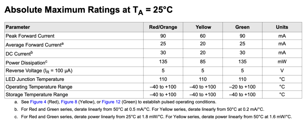
First let’s check the maximum rating for the component. Looking at the datasheet, we see the following table:

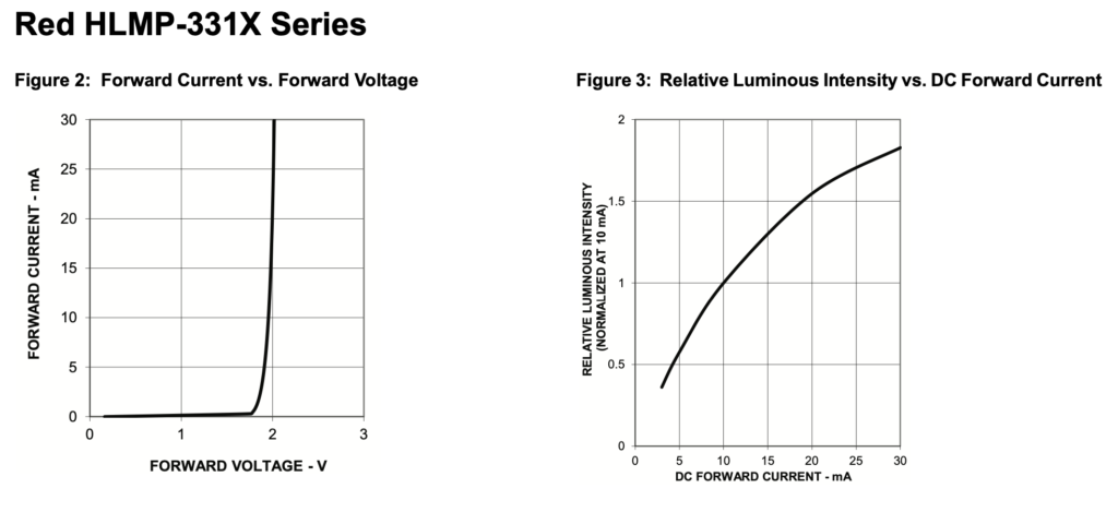
We can see that the maximum DC current for a red LED is 30mA. We generally don’t want to run a component right on its maximum limit, so what happens if we reduce the current a bit? Digging further on the datasheet, we find the following graphs:

The graph in figure 3 shows us how bright the LED will be at various currents. At 10mA, the intensity of the LED light is said to be at a normalised level of 1. If we increase the current to 20mA, then the LED will be around 1.5 times as bright as the 10mA level. Increasing the current to 30mA (the max) then the intensity is only around 1.8 times as bright at the intensity at 10mA, so it is consuming a lot more power for little gain. At 20mA, we still get a bright intensity while leaving a fair amount of headroom below the maximum, so let’s design our circuit to have a current:
What will be the voltage across the LED at that current? Referring to the graph in figure 2, we see that the voltage across the LED will be approximately:
\[V_{f_{LED}}=2\text{ V}\]
What will be the voltage across the resistor of R ohms? We know the current through the resistor must be 20mA, so we can use Ohm’s law to work out the voltage drop across the resistor:
\[\begin{align*} V_R & = i \times R \\ & = 20 \times 10^{-3} \times R \end{align*}\]
We can now use Kirchoff’s voltage law, which says the sum of voltages in a loop is always equal to 0V. If we go clockwise around the circuit, the voltage source helps the current and is therefore positive, whereas the resistor and LED oppose the current, so their signs are negative. The equation becomes:
\[\begin{align*} V - V_R - V_{f_{LED}} & = 0 \\ V - i \times R - V_{f_{LED}} & = 0 \\ i \times R &= V - V_{f_{LED}} \\ R & = \frac{V - V_{f_{LED}}}{i} \end{align*}\]
If we assume we are using a 9V battery, then substituting in the numbers gives us:
\[\begin{split}R & = \frac{(9 - 2)}{20 \times 10^{-3}} \\ & = 350~\Omega\end{split}\]
For safety, we can round it up to the nearest preferred value, which would be a 390Ω resistor with colour code orange-white-brown. Double-checking the current, we get:
\[\begin{split} i & = \frac{V - V_{f_{LED}}}{R} \\ & = \frac{(9 - 2)}{390} \\ & = 18\text{ mA}\end{split}\]
This is still acceptable. So, we have now completed our circuit design: